
- #SPDT RELAY IN PROTEUS LIBRARY PDF#
- #SPDT RELAY IN PROTEUS LIBRARY CODE#
- #SPDT RELAY IN PROTEUS LIBRARY SERIES#
**Vin pin of Arduino can supply maximum current = 200mA. If both relays are energized, current= 30*2=60 mA So current need to turn on the relay = 12/400 Amps = 30 mA Resistance of relay coil is measured using a multimeter which turn out to be = 400 ohms
#SPDT RELAY IN PROTEUS LIBRARY SERIES#
MOSFET is switched on and off at high frequency voltage and since motor is connected in series with the drain of MOSFET, PWM value of voltage determines the speed of motor. MOSFET is required to control the speed of motor.
#SPDT RELAY IN PROTEUS LIBRARY CODE#
Check the complete Arduino Code at the end.
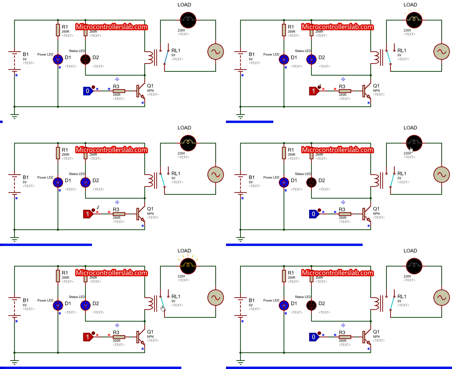
To control the Speed of DC Motors with Potentiometer using Programming. To provide the amount of current required to turn on relay. Hence transistors are used to conduct current from Vin pin of Arduino to relay which is controlled using a push-button connected from digital pin to base terminal of transistor. Vin pin of Arduino cannot easily supply this much current for both relay. Besides we are using 12v relay in this project. ** if you have two separate 12 v battery then connect one battery’s positive terminal to the negative terminal of another battery and use remaining two terminals as positive and negative.ĭigital pins of Arduino cannot supply the amount of current needed to turn on a normal 5v relay. Connect Potentiometer's end terminal to 5v pin and Gnd pin of Arduino respectively. Connect diode across relay exactly as shown in figure. Digital pin 2 and 3 of Arduino, each one in series with pushbutton, goes to base of transistors. Connect emitter terminal of both transistor to GND pin of Arduino. Out of two remaining terminals, one goes to the Vin pin of Arduino Uno and other to the collector terminal of transistor (for each relay).  Connect motor in between the middle terminal of relays. Connect 10k resistor from gate to source and 1N4007 diode from source to drain. Connect source of MOSFET to negative terminal of battery and to Ground pin of Arduino UNO. Connect normally open terminal of both relay to drain terminal of MOSFET. Connect normally closed terminal of both relays to positive terminal of battery. Transistors (2N222A) were used to apply sufficient current to the relays. The use of latching switches allowed for reduced power consumption, because they require a pulse for activation rather than a continuously applied voltage. Latching SPDT relay switches (Omron G6EK-134P) were used to electronically isolate the output devices from each other and the input switch. The PIC can determine the amount of time the switch is held, and then either change devices or continue to operate the current device. The Switch Relay circuit is based on a PIC microcontroller (Microchip, Inc., Chandler AZ), which detects the activation of the user’s switch. The coordinator of the project states that “the device will enable people with limited physical ability to independently operate multiple devices.” The use of only one switch to operate a pair of devices also minimizes confusion for the user.īecause of the adjustable “hold time,” devices with different activation times can be operated therefore, almost any switch activated device can be controlled with the Switch Relay. An LED readout shows which device is being controlled.Īllowing operation of multiple devices with one switch increases the independence of the user.
Subsequent switch presses that are longer than the minimum duration will toggle control of the Switch Relay between the two devices. A knob allows the client to adjust the minimum pressing duration to 0.5 to 8 secs, in 1 sec increments. However, when the client presses the switch for a minimum duration of time, the device toggles its state so that the switch now controls a second device. Pressing and releasing the switch will directly control the first device. The Switch Relay was designed to give clients control over two different switch-activated devices using only one switch.
#SPDT RELAY IN PROTEUS LIBRARY PDF#
Pic10f series microcontroller based Project List of PDF. Pic16f72 microcontroller based Project List of PDF. PIC32 microcontroller based Projects List of PDF. Pic18f452 microcontroller based projects list PDF. Pic18f4550 microcontroller based projects List PDF. Pic16f877 based projects – PIC Microcontroller PDF Downloadable. Proteus based Pic Microcontroller Projects pdf. Pic10f series microcontroller based Project List. Pic18f452 microcontroller based projects. 
Pic18f4550 microcontroller based projects. Pic16f877a microcontroller based projects list.


 0 kommentar(er)
